
The DR4 is a specific optical transceiver interface type, available in the QSFP-DD (Quad Small Form Factor Pluggable – Double Density), supporting an aggregate transmission rate of 400G. With a reach of up to 500m over single-mode (SM) fiber, its primary application is high-speed intra-data center connectivity. This article will provide a comprehensive description of the important features and attributes of this important new technology.
DR4 Versus Other 400G Interface Types
Before we dive into the deep end on the DR4, let’s review some other popular 400G interface types. In the interest of brevity, this list is limited to 400G interfaces with 100G optical channels (we will take on 400G interfaces with 50G optical channels in a separate post). The following table lists the key attributes that define and differentiate these interfaces:
| Interface Type | Nominal Wavelength (nm) | Fiber Type | Reach | Optical Signal Rate | Electrical Signal Rate | Optical Connector |
| DR4 | 1310 | SM | 500m | 4x100G | 8x50G | MPO-12* |
| FR4 | 1270, 1290, 1310, 1330 | SM | 2km | 4x100G | 8x50G | Duplex LC |
| LR4 | 1270, 1290, 1310, 1330 | SM | 10km | 4x100G | 8x50G | Duplex LC |
*Other alternatives are emerging as alternatives to the MPO-12 (discussed below)
The DR4 is differentiated from the FR4 and LR4 in three critical respects: nominal optical transmission wavelength, reach, and optical connector. The DR4 supports 4 x 1310nm full-duplex 100G optical transmission lanes. Each direction of each lane is carried on a separate fiber, 4 x Transmit (Tx) and 4 x Receive (Rx). These 8 optical streams are connected to an external fiber ribbon cable via an integrated MPO-12 optical connector. The reach of the DR4 is the shortest of the three at a maximum of 500 meters. The FR4 and LR4 use 4 different CWDM wavelengths in the O-band (Original band, 1260nm-1360nm) for transmission of their 4 full-duplex 100G lanes. These devices include an integrated CWDM Mux to combine (Tx direction) these 4 wavelengths onto a single fiber and a CWDM de-mux to separate them on the Rx side. The optical connector on the FR4 and LR4 interfaces is duplex-LC. The reaches of the FR4 and LR4 are 2km and 10km, respectively.
400GBASE-DR4 – Under the Hood
Now let’s take a look “under the hood” to see the main components of the transmission path inside a 400G DR4.
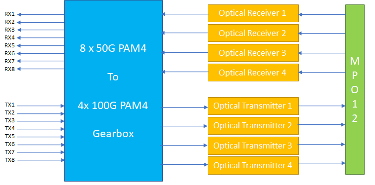
The left side of this block diagram shows the 50G electrical lanes connecting to the host system into which the 400G DR4 module is installed. The right side shows the MPO-12 connector into which the fiber ribbon cable is inserted. The blue block is circuitry (ASIC), referred to as a ‘gearbox’ the purpose of which is to combine 2 x 50G lanes into one 100G lane in the Tx direction and separate a single 100G lane into 2 x 50G lanes in the Rx direction.
Standards Defining the 400GBASE-DR4
Several standards apply to define the attributes necessary to create multi-vendor plug-and-play 400GBASE-DR4 optical transceivers, as follows:
- QSFP-DD MSA – This Multi-Source Agreement (MSA) defines the electrical and optical connections, electrical signals, power supplies, mechanical and thermal requirements of the pluggable QSFP Double Density (QSFP-DD/QSFP-DD800). It builds on the prior QSFP form factor, connector and cage system.
- IEEE 802.3bs – This standard defines the 400GAUI-8 (GAUI – Gigabit Attachment Unit Interface) defining electrical clock and data interface between the 400G DR4 and the host system
- OIF CEI-56G-VSR-PAM4 – The Optical Internetworking Forum CEI-56G-VSR-PAM4 (Common Electrical I/O, 56Gbps, Very Short Reach, Chip-to-Module, PAM4 Modulation) standard, or Implementation Agreement in OIF parlance, defines the SERDES (Serializer/De-serializer) function, including PAM4 modulation, for compatibility across the QSFP-DD to Host interface.
Optical Connector
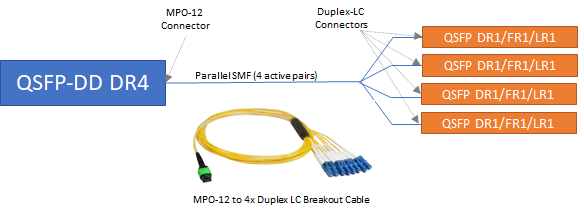
As stated in the table above the MPO-12 is the standard optical connector defined for the QSFP-DD 400G DR4. One of the advantages of this arrangement is each of the four component 100G lanes may be split out and connected to a different 100G DR1 (or FR1, LR1) interface at the other end. This helps greatly as data centers migrate from 100G to 400G. This is accomplished by using an MPO-to-4xDuplex-LC cable as shown below.
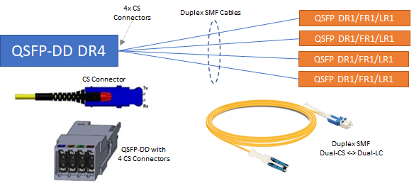
An alternative breakout arrangement is beginning to emerge utilizing a new type of optical connector called a “CS” connector. This connector is ½ the height and ½ the width of the ubiquitous LC connector. This level of miniaturization allows 4 duplex CS connectors to be integrated into the QSFP-DD package, as shown in the figure below. Using this technology, breakouts are much simpler and more flexible. Each duplex CS and connected to the desired QSFP DR1, FR1 or LR1 using duplex-CS to duplex-LC optical patch cables of whatever length required for each link (more flexible than the single MPO-4xLC breakout cable, above).
Conclusion
The QSFP-DD 400GBASE-DR4 optical transceiver is an excellent choice for high-speed interconnection with commercial and enterprise data centers. The DR4, versus the FR4 and LR4 alternatives, is especially useful when interconnecting newer equipment with 400G QSFP-DD slots with prior generation with 100G QSFP28 slots. This advantage is due to its 8-fiber parallel optical fiber interface. Each Tx/Rx pair of this interface may be connected to a different 100G QSFP28. The interconnected 100G ports may be equipped with DR1, FR1 or LR1 interfaces, however, in all cases, these links are limited to the 500 meter maximum supported by the DR4. Feel free to browse Fluxlight’s wide array of 400G Optical Transceivers and start building bigger, faster optical networks sooner than you may have imagined.