
The FEC described in this article is an acronym short for Forward Error Correction. Not to be confused with its homophone, “feck”, meaning “effect”. That said, the two may in a certain sense be related. Although in the Scots dialect of Middle English the term feck was used on its own, in modern English use it includes the suffix, “less”, so “feckless”. Feckless refers so something (often someone) being without effect, ineffective…without purpose.
Ok, stay with me now. Over the past several years, various groups (IEEE, OIF, various MSA bodies) have worked diligently defining standards for reliable transmission of 400G+ links in a multi-vendor pluggable optical transceiver environment. To meet these challenges, higher-order modulation schemes, notably PAM-4, have been adopted that, all else being equal, result in lower Signal to Noise Ratios (SNR) and higher Bit Error Rates (BER). Forward Error Correction (FEC) is technique to reduce the effective BER on these noisy channels by up to 8 orders of magnitude… from 2.4E-4 to less than 1E-12. That’s going from several bit errors in every 10 thousand bits to less than one error in 1 trillion bits!
To put this in perspective, a 2.4E-4 BER channel is essentially out-of-service. So, when it comes to 400G optical channels, being FEC-less is feckless!
What is FEC?
FEC used to detect and correct a certain number of errors (single and burst errors) by adding redundant bits and error-correcting codes to each block of data before transmission. These additions contain sufficient information to enable the FEC decoder at the receive end to recover the original message error free. While FEC adds overhead with its additional, redundant data, its value is in avoidance of entire errored frames, saving bandwidth and delay otherwise required for retransmission.
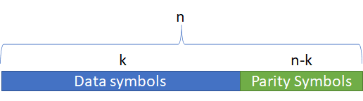
FEC uses ‘n’ symbol codewords consisting of the actual data block being transmitted that is ‘k’ symbols long and a parity block that is n-k symbols long, as shown in the figure below. A given FEC coding scheme is thus described by the ordered pair (n,k).
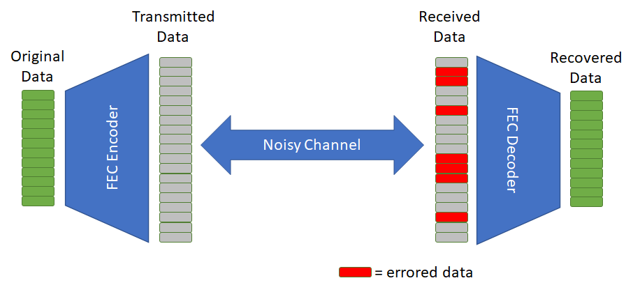
The following diagram shows one direction of a transmission with FEC coding and decoding. If the number of bit errors are within the limits of the specific FEC coding scheme in use, the original data can be recovered in spite of these errors.
FEC for 400G Optical Transmission
FEC based on Reed-Solomon codes is used for the PAM-4 channels in 400G optical links. What is known as KP-FEC has been specified in the IEEE 802.3 standard for PAM-4 signals. KP-FEC can be applied to both 100G (KP1) or 400G (KP4) signals. KP1-FEC is applied to PAM-4 signals to group two 50-Gbit PAM-4 electrical signals into a single 100GBASE-KP1 encoded signal. KP1-FEC translates 30 parity symbols, in which each symbol consists of 10 bits. This parity string gets appended to a 514-symbol data field (k) to form a 544-symbol encoded codeword (n), so KP1-FEC is denoted as RS(544,514). KP-FEC has the potential to correct up to 15 symbols per codeword.
Conclusion
The PAM-4 signals used in QSFP-DD optical transceivers have a tighter spacing between voltage levels, reducing the eye amplitude to one-third that of a similar NRZ signal. This results in the PAM-4 signal having a lower SNR and being more susceptible to noise. To compensate for the reduced SNR, 400G standards have defined KP-FEC, RS(544,514) for these channels. Without the use of FEC, many 400G channels would have too high a Bit Error Rate (BER) for reliable communication. Said another way, 400G PAM-4 channels would be feckless without FEC!